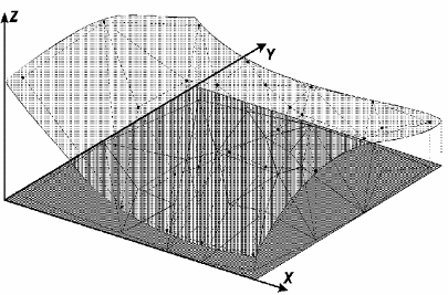
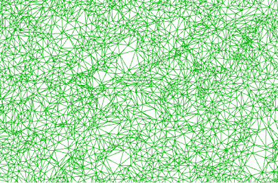
In surface modeling through triangle irregular grid, each polygon of a polyhedron face is a triangle. The triangle vertexes are generally surface sampled points. This modeling, considering triangle sides, allows that important morphological information such as discontinuity represented by linear shapes of tops and valleys are considered during triangle grade generation, making possible model a terrain surface keeping surface geomorphic shapes.
The redundancy number is drastically reduced if compared to the rectangle grid, once the grid is thinner in regions of big variations and more spaced in almost plane regions. Surface discontinuities can be modeled through characteristics lines and points.
This grid has the advantage to use its own sampled points to model the surface, with no need of any type of interpolation. The disadvantage of irregular grid is the procedures to obtain data from triangle grids tend to be more complex and consequently slower than the rectangle grid.
Example:
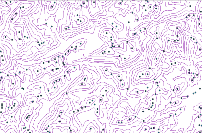
Input Samples and Isolines:
Output TIN:
It is
accessible through:
PROCESSING
→ DTM
PROCESSING
→ TIN GENERATION...
1. Select Input Layer(s)
 to select a isolines
and/or samples layer. If you are not going to use both types of layer
leave one blank, but one type should be selected.
to select a isolines
and/or samples layer. If you are not going to use both types of layer
leave one blank, but one type should be selected.5. Break Line
6. Line Simplification: data preprocessing phase values that are calculated initially from the defined scale of the layer. Parameters can be:
 to select output layer SRS. to select the output
directory
and also inform the new layer name to store the result, or
to select output layer SRS. to select the output
directory
and also inform the new layer name to store the result, or to select
the Data Source
and Inform
the new Layer
Name to store the aggregation result.
to select
the Data Source
and Inform
the new Layer
Name to store the aggregation result.